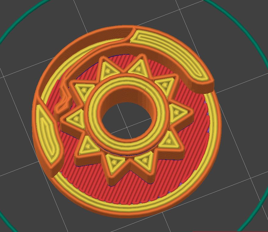
After half a dozen iterations, this was the first reasonably working, acceptable feeling, and good-sounding ratchet mechanism.
allows clockwise rotation blocks counterclockwise rotation
design features:
- allows for a large inner bore (e.g. rotary encoder shaft or 5.2mm screwdriver bit)
- printable with 0.4mm nozzle
- 2cm diameter
- no assembly required. Print in place.
To get a full ratchet: mirror the assembly and add a mechanism/part that pushes one of the springs out. In neutral both leavers are engaged and the ratchet is completely locked.
Btw. Good luck copying it without going through half a dozen of iterations. Going from it barely works to this isn't easy. For my part: Version 5 was working and close to the final design. It took another 10 rounds to get it usable and from there some more to fine-tune it.
I wish I could see a visual of how it operates, because I'm sure it's something simple about it that I'm not seeing right away.
The thing that I'm having trouble comprehending is how the symmetrical teeth design would be capable of engaging the spring/blocker (pawl?). I mean that the pawl doesn't seem like it will be able to work as a stop; it seems like it would just allow the gears to bypass it regardless of rotation direction. Is this incorrect? I know you said there is a mirrored assembly to block the rotation in the other direction, but that still doesn't help me understand the pawl/teeth engagement quandary that my mind has created.
The sound signature you mentioned is a nice detail that I'm glad you included. I definitely wouldn't have thought of that right away if I was designing something similar.
here you go: https://www.thingiverse.com/thing:6595547 Likely a old version with 0.4mm clearance that does work. If not message me and I could send you a later revision with 0.23mm that definitly works.
How does it work?
one direction: pretty obvious the spring bends out, the teeth pass through the other direction: the spring gets slightly pulled/stretched (the leading tip of the teeth pushes it) which causes the tip to be pushed against the block (left in the picture) and blocking the mechanism.
In other words, this mechanism works by having a physical path for the compression of the spring but in the opposite direction when would need to stretch to move pass the teeth it is stopped by a wall/block.