Our kids are starting to outgrow our double stroller, but will still want to ride from time to time. We've had this wagon for years, but it needed some upgrading. Rather than toss it and buy a new kid wagon, I decided to modify this one. Its biggest deficit was its wheels. They had metal sleeve bushings instead of real bearings and the wheels themselves were basically just an ABS doughnut with a narrow/thin rubber bands for tread. The treads had all cracked and fallen off. All this made the wagon hard to pull and loud.
I decided to make my own wheels to solve both problems. The new wheels consist of two halves and a TPU tread. The halves are keyed to mate with each other and are held together with m3 nuts/threadserts. Each half contains two skate bearings, resulting in four bearings per wheel. It's probably overkill, but I didn't want to leave the two halves unsupported in the center of the wheel at their interface.

Built in bridges for the somewhat weird shape to trick the slicer.

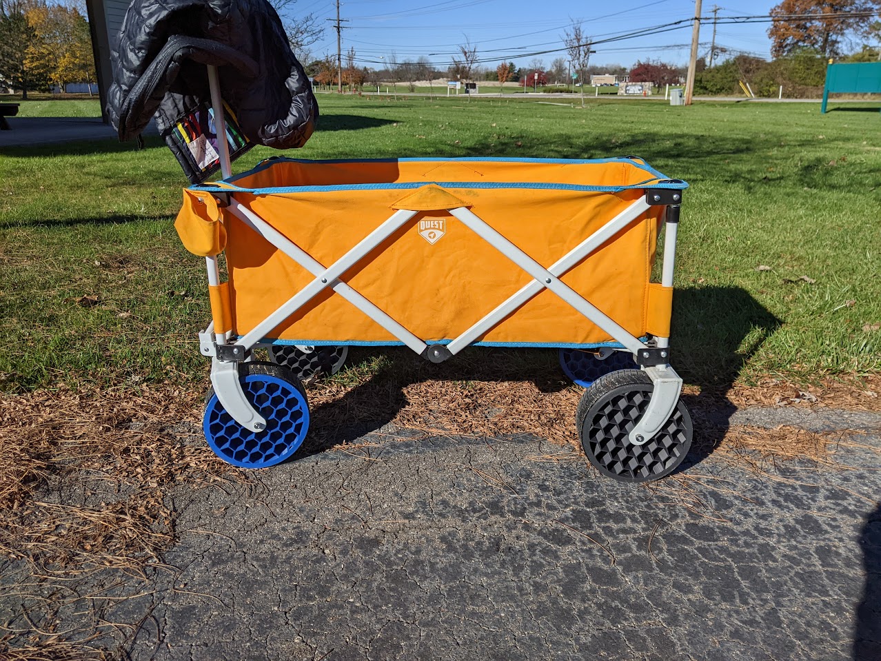
Now my 3 year old can pull me around in the wagon.
I’m still confused about the bridges everyone’s talking about. Please help
This is buried lower in the thread, so here it is again: the face you see facing you in the CAD was the first layer. Note the inset faces at 1:00, 3:00, 5:00, 7:00, 9:00 and 11:00. Due to their shape and the fact that they have a hole in the middle of them, a slicer would typically just try to print from the center out in mid air.
Orienting the print the other way around wouldn't have worked due to the way I decided the two halves to mesh - I would have been printing way more in mid air. This orientation also gives me a nice looking first layer facing out.
@alkheemist@aussie.zone was right on the money, here are a few closer visuals. They're only a layer thick. I've found that if I make them too wide the slicer will stop trying to turn them into a bridge.
CAD:
Here's one of the earlier ones before I got the spacing down. Without it my slicer would have tried to print the circular heatsert hole in midair.