this post was submitted on 15 Apr 2024
87 points (93.9% liked)
3DPrinting
15124 readers
160 users here now
3DPrinting is a place where makers of all skill levels and walks of life can learn about and discuss 3D printing and development of 3D printed parts and devices.
The r/functionalprint community is now located at:
!functionalprint@kbin.social
or !functionalprint@fedia.io
There are CAD communities available at:
!cad@lemmy.world or !freecad@lemmy.ml
Rules
-
No bigotry - including racism, sexism, ableism, homophobia, transphobia, or xenophobia. Code of Conduct.
-
Be respectful, especially when disagreeing. Everyone should feel welcome here.
-
No porn (NSFW prints are acceptable but must be marked NSFW)
-
No Ads / Spamming / Guerrilla Marketing
-
Do not create links to reddit
-
If you see an issue please flag it
-
No guns
-
No injury gore posts
If you need an easy way to host pictures, https://catbox.moe may be an option. Be ethical about what you post and donate if you are able or use this a lot. It is just an individual hosting content, not a company. The image embedding syntax for Lemmy is 
Moderation policy: Light, mostly invisible
founded 1 year ago
MODERATORS
In a broader picture: See it as a demonstration of what all those nice tools in the CAD package can do. In this application with a little bit of thought could come up with a similar or better solution but for an I don't care design approach the output is already good. A proper design approach would be putting thought in in where to place the contact surfaces relative to the spool and then run this software or go a step further and allow a different software to also change that parameter. Keep in mind those simulations are computationally expensive. Complex/advanced questions might take days to solve while a simple question like this is less than 1 minute.
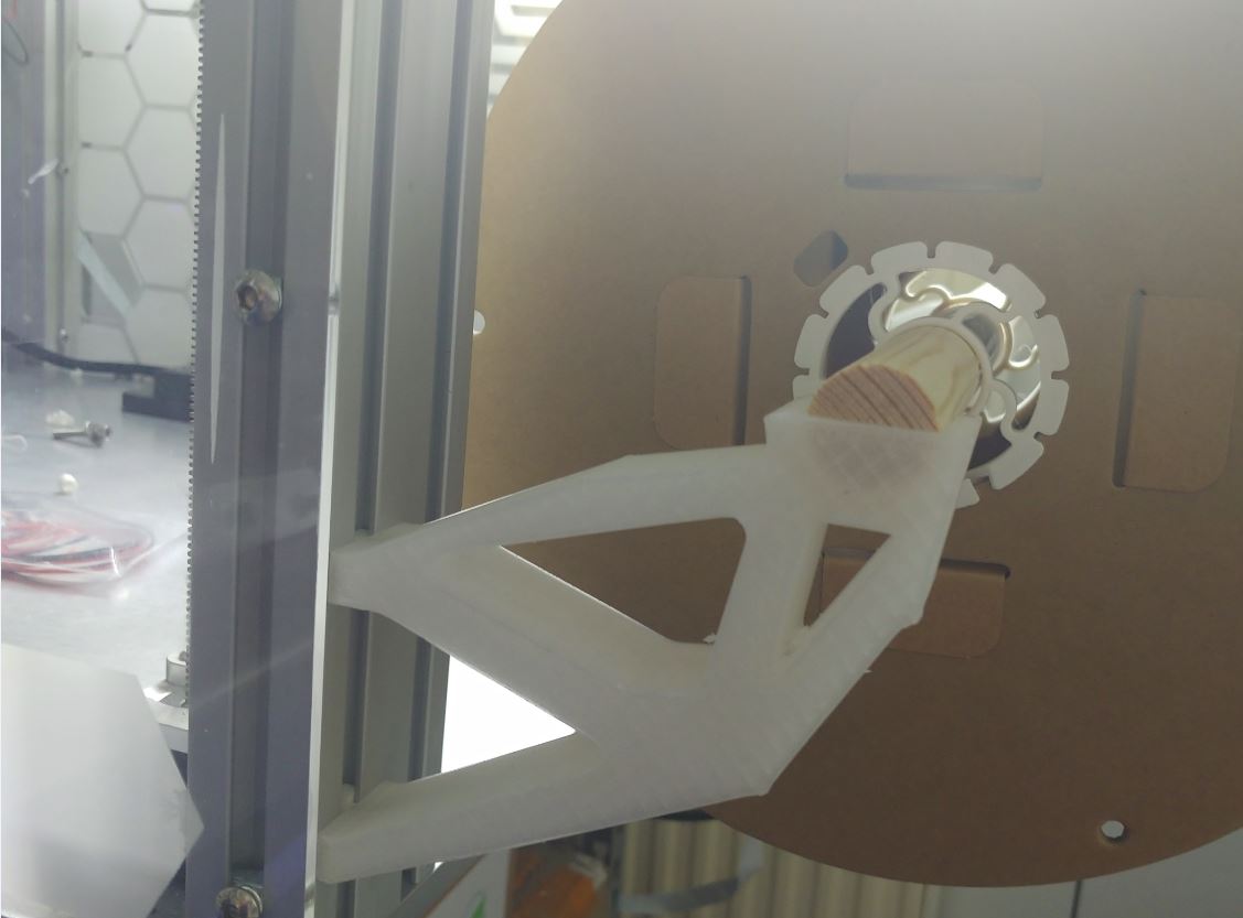
The load was in the circle/groove facing down.
The other constrain was the faces contacting the 3030 extrusion being fixed and a keep-out zone was defined around those to ensure no material there was removed.
Otherwise, it was just a flat slab as shape.
What at first surprised me was how this part works: There is a point defined by the lowest/left triangle (tension & compression) on which all the weight rests. The remaining structure is is a cross beam (top mounting point to spool) to support it (tension) and the structure on which the spool rests (compression).